Article Overview
Attenuation in fiber optics is the loss of signal strength as light travels through the fiber, influenced by absorption, scattering, and fiber design, with core count affecting overall cable performance but not the intrinsic attenuation per fiber.
Understanding Attenuation
Attenuation is measured in decibels per kilometer (dB/km) and represents the gradual reduction of light signal strength as it propagates through the fiber. The primary intrinsic causes are absorption and scattering. Absorption occurs when light energy is converted to heat by molecules in the glass, primarily due to residual hydroxyl ions (OH⁺) and dopants used to modify the refractive index. Scattering, especially Rayleigh scattering, arises from microscopic density variations in the glass, causing light to deviate from the core and escape into the cladding or back toward the source. Scattering losses decrease with longer wavelengths, which is why 1550 nm signals travel farther than 850 nm signals in standard fibers . Extrinsic factors such as macrobends (large visible bends) and microbends (microscopic deformations) also contribute to attenuation. Modern fibers, including bend-insensitive types, are designed to minimize these losses .
Core Count and Its Effect
The core count refers to the number of individual optical fibers bundled within a single cable. While each fiber maintains its intrinsic attenuation characteristics, higher core counts can influence overall system performance in several ways:
- Crosstalk and interference: Closely packed fibers may experience slight optical interference, though modern cable designs minimize this effect.
- Connector and splice losses: More fibers mean more terminations and splices, which cumulatively add to the total link attenuation.
- Cable diameter and bending: High-fiber-count cables are often thicker and less flexible, potentially increasing macrobend losses if not properly installed . Each fiber in a high-core-count cable typically retains the same attenuation per kilometer as a single fiber, e.g., 0.22 dB/km at 1550 nm for single-mode fibers like Corning SMF-28 Ultra . Therefore, the intrinsic attenuation is independent of core count, but the total system loss can increase due to additional connectors, splices, and handling challenges.
Practical Considerations
- Single-mode vs. multimode: Single-mode fibers have lower attenuation and are preferred for long-distance transmission, while multimode fibers are more affected by modal dispersion and slightly higher attenuation .
- Wavelength selection: Operating in low-loss windows (850 nm, 1300 nm, 1550 nm) minimizes intrinsic attenuation .
- Installation care: Proper routing, avoiding tight bends, and using bend-insensitive fibers reduce extrinsic losses, especially in high-core-count cables . In summary, attenuation per fiber is largely independent of core count, but high-core-count cables require careful design and installation to prevent cumulative losses from connectors, splices, and bending. Selecting appropriate fiber types, wavelengths, and installation practices ensures optimal performance across all cores.
Specifications For Fiber Optic Networks
The Fiber Optic Association - Reference Guide Specifications For Fiber Optic Networks Per current standards and specs, maximum
Attenuation in Fibers
This is a continuation from the previous tutorial - graded-index fibers. Several factors contribute to attenuation of the power of an
Recommendation ITU-T G.652 (08/2024)
Cable attributes focus on attenuation coefficient and polarization mode dispersion coefficient, with
Basics of Fiber Optics
Lower loss: Optical fiber has lower attenuation (loss of signal intensity) than copper conductors, allowing longer cable runs and fewer
The FOA Reference For Fiber Optics
Optical fiber attenuation is sensitive to stress like encountered when bending fiber too tightly, especially with patchcords and fibers in
OPTICAL FIBER COMMUNICATION
Single Mode Fibers With the primary degrees of freedom of core cladding diameter and the difference of refractive indices between
Introduction to Optical Fibers, dB, Attenuation and Measurements
Optical fiber is a medium to carry information. It is made of silica-based glass. It consists of a core surrounded by
Broadband optical fibre with an attenuation lower than 0.1
Microstructured air-core optical fibre provides unprecedented low-loss transmission of light signals over a broad
Attenuation In Optical Fibers And Calculation
Optical fiber is our first topic of discussion here. So, let''s get started with the basics of attenuation and see how fiber
Attenuation Factor Calculator
Attenuation Factor Calculator This is an online calculator that calculates the Attenuation Factor of an Optical Fiber. Just enter the
Performing Fiber-Optic Cable Attenuation Measurements: A Tutorial
Measuring attenuation in a fiber-optic cable is a vital ingredient to obtaining the maximum performance from a system
Fiber Attenuation Coefficient
Fiber attenuation coefficient is defined as a measure of how much optical power is lost per unit length of optical fiber,
Attenuation
Attenuation determines either how much fiber you can use in an application or how much light your optical source must produce.
Theory of Dispersion and Attenuation of Light Wave
A fiber-optic cable consists of one or more optical fibers having slightly less refractive index
Fiber Optics Calculator | Attenuation, Dispersion, NA, V-number —
Calculate fiber optic parameters: attenuation, pulse broadening, bandwidth, NA, V-number, and mode classification. Free online tool
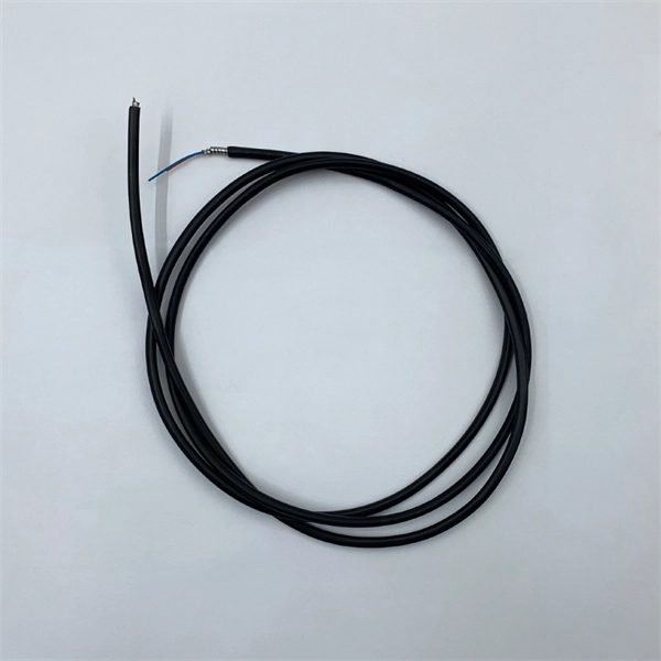
How Many Core In Fiber Optic Cable Do I Need
The number of fiber cores mainly depends on interface of fiber connection equipment and type of the device,read
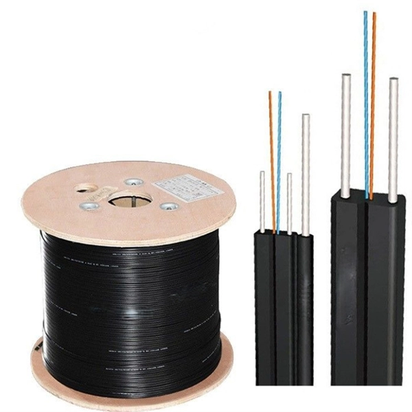
Fiber Optic Attenuation Calculator | Fiberopticx
3. Number of Connectors: Connectors are used to connect fiber optic cables. Each connector introduces some insertion loss, which
What Is Attenuation in Fiber Optics and How Is It Measured?
Attenuation causes light to weaken as it travels through fiber optic cables. Learn why it happens, what affects it, and
Fiber-Optic Cable Signal Loss, Attenuation, and Dispersion | Juniper
Attenuation and Dispersion in Fiber-Optic Cable Correct functioning of an optical data link depends on modulated light
Hollow-Core Optical Fibers for Telecommunications and Data
Hollow-core optical fibers (HCFs) have unique properties like low latency, negligible optical nonlinearity, wide low-loss
Intrinsic and Extrinsic Attenuation in Fiber Optic Cables
Attenuation limits the distance in which the signal can travel through optical fiber and is
Fiber Attenuation
Optical attenuation in an optical fiber is one of the most important issues affecting all applications that use optical fibers. A number of
fiber loss limits
Fiber loss, or attenuation, refers to the reduction in optical power as light travels through a
What Is the Attenuation Coefficient? Why Some Fibers Lose Less Signal
4. **Technological Innovations:** Continuous advancements in fiber optic technology, including the development of
Understand Fiber Attenuation
Fibers with a high numerical aperture and low core/clad ratio are least susceptible to macrobend losses. Understanding
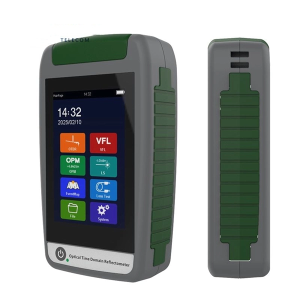
Fiber Optic Calculators | FSI Technical Tools
Utilize FSI''s specialized fiber optic calculators for precise planning and design. Optimize your projects with our accurate, easy-to-use
Basic Principles of Fiber Optics Series: Attenuation
Discover the causes and effects of attenuation in fiber optic cables. Learn about scattering,
Guidelines Corning Recommended Fiber Optic Test
3. Tier 1 and Tier 2 Testing c systems. The two tiers of testing are Tier 1 required. This level of testing consists of link attenuation